Basics of bike's electrical system
A motorcycle cannot operate without a functioning electrical system. It is therefore all the more important to understand watts and volts, amps and ohms.
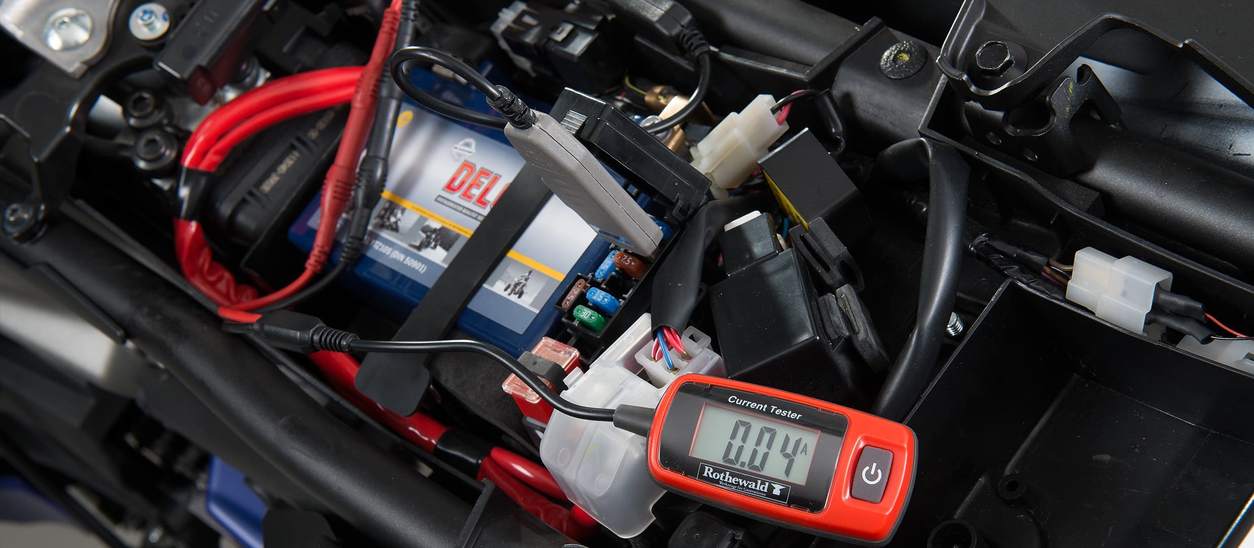
Electrical System Basics
When it comes to the electrics of your machine, the words “watts”, “volts” and “ohms” can make you practically dizzy. To be able to successfully repair electrical defects at the vehicle, the mechanic must be familiar with and understand these words and also a number of additional important fundamental physical principles of electrical systems. Here we'll explain watts, volts and so on for our DIY mechanics, and also allay the widespread fear of working on the electrical system of the motorcycle.
Current is invisible – however its effect can be perceived by the senses: e.g. the light from a bulb, heat from a heated grip or deflection of a voltmeter clearly show that current is flowing.
"Current flow" in the DC system of a motorcycle means that negatively charged electrons migrate from the negative terminal of the power source (e.g. battery) via a cable and a consumer (e.g. a bulb) to the positive terminal. With alternating current, the current direction changes continuously – unrectified current flows e.g. from the AC alternator to the voltage regulator/rectifier unit of the vehicle where it is rectified and fed from there into the DC electrical system.
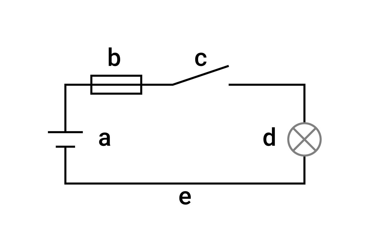
Circuit with fuse: a) Power source (battery); b) Fuse; c) Switch; d) Consumer (bulb); e) Cable
The fundamental definitions: ohm, volt, amp and watt
The intensity of the current and effect of a conductor can be explained by comparing it to the flow of water in a pipe. The water pressure at the end of the pipe depends on its diameter and – the higher up the water source is and the greater the diameter of the pipe, the greater the water pressure will also be.
With current flow, the cross-section of the connected electrical cable corresponds to the diameter of the pipe. The thicker and shorter the cable is, the more effectively it conducts current, and therefore the less "resistance" the current encounters. The longer and thinner the cable is, the higher its "electrical resistance" will be. This depends on the material, cross-section, length and temperature. The resistance is measured in ohms (Ω) and uses the formula symbol R. The cable is made of metal and does not conduct the current completely smoothly. This friction produces heat. If the cable is too thin or corroded, it can become considerably hot and even cause the insulation to burn (cable fire). To avoid this kind of damage, electrical fuses are used. They work in a similar manner to a predetermined breaking point on a mechanical component, by interrupting the circuit, e.g. in the event of a short-circuit. They therefore prevent damage to the battery and electrical components and also cable fires.
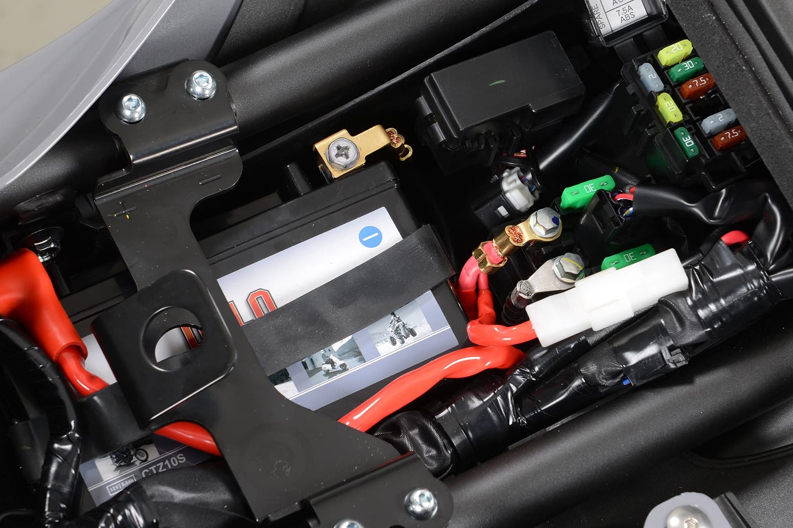
Ensure the connections are clean and corrosion-free at all times
In addition to ensuring the cables are thick enough for the relevant application, contacts, such as terminals and connectors should be kept free of corrosion and soiling to keep the contact resistance as low as possible. Use of terminal blocks and branch connectors on the vehicle should be avoided whenever possible as they increase the resistance in the cable unnecessarily and do not establish a safe and vibration-proof connection. The quality of negative/earth cables should be as good as positive cables.
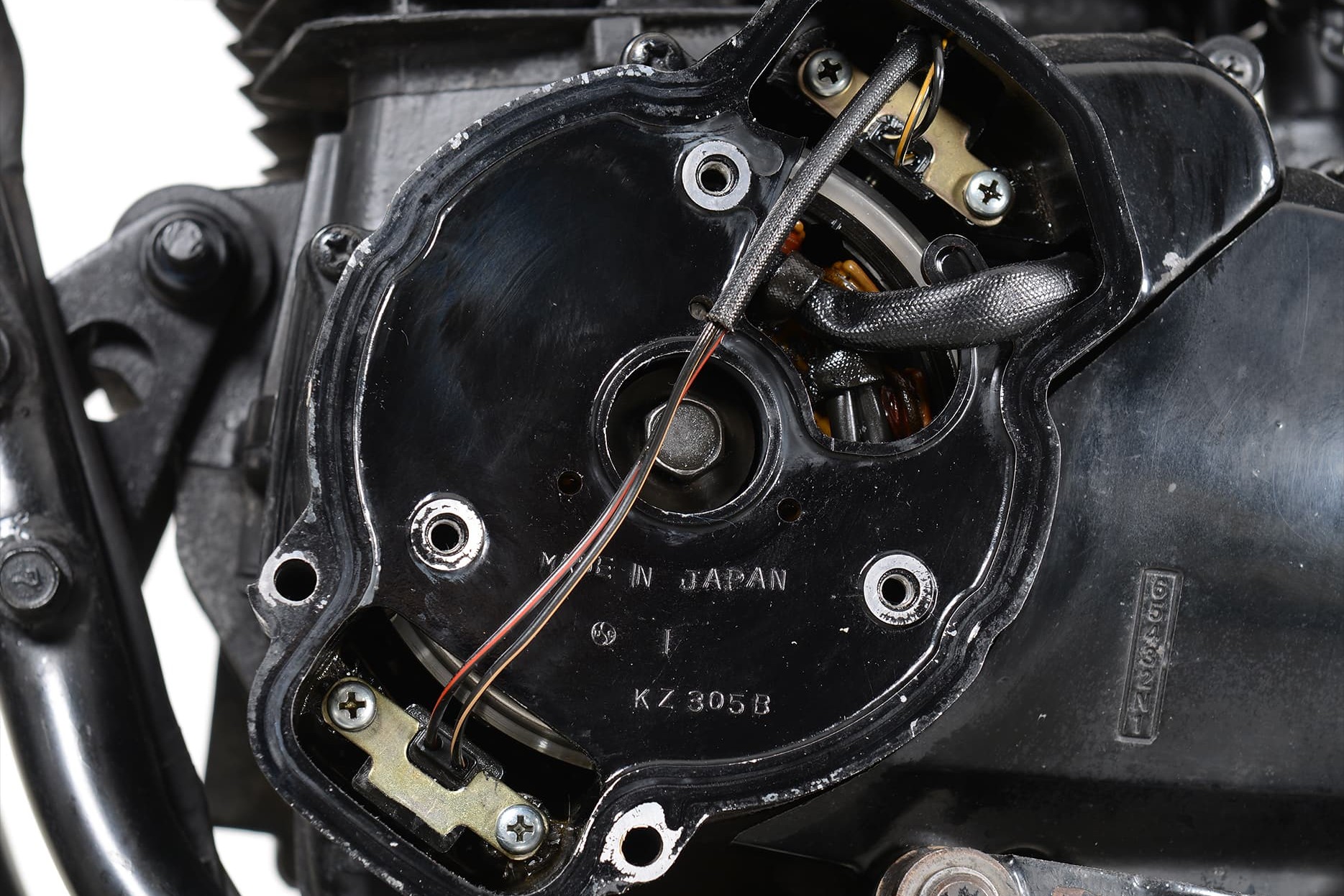
The alternator: where power is generated
The voltage is measured in volts (V) and has the formula symbol U. The voltage is the potential difference between the negative and positive terminal: In our water analogy, this is the difference between a full and an empty tank on the same level connected by a pipe. The water flows between tanks until the fill level is the same in both tanks. This condition corresponds to a discharged battery. In order for the water to flow again, it must be transferred/pumped from one tank to the other; in the case of the battery this is done by a charger or power generator, referred to as the "alternator" of the vehicle. This generates voltage through the rotational movement of an electrical coil in a magnetic field.
Another important factor in the circuit is the amperage. This is measured in amps (A) and has the formula symbol I. The amperage states how many electrons flow through a conductor cross-section/resistor (power cable) over a specific time. In our water analogy, the amperage corresponds to the quantity of water that flows through the pipe for a specific time, which depends on the pipe diameter and gradient.
The correlation between the physical variables described up till now (amperage, voltage and resistance) is described by Ohm's Law:
- R = U / I (Resistance = Voltage / Amperage)
- I = U / R (Amperage = Voltage / Resistance)
- U = R x I (Voltage = Resistance x Amperage)
If two variables are available, the third variable can be calculated from these. The fourth important variable which is required to describe an electrical circuit and the efficiency of an electrical consumer is power. It is specified in watts (W) and has the formula symbol P. It is also influenced by the voltage and amperage and can be calculated using the following formula:
- P = U x I (Power = Voltage x Amperage)
- I = P / U (Amperage = Power / Voltage)
- U = P / I (Voltage = Power / Amperage)
In an electrical circuit, current only flows if it is also closed. As already discussed, an electrical circuit basically consists of voltage source, cable and one or several consumers. A single-conductor system is normally used in motorcycles, i.e. one cable connects the positive battery terminal to the relevant consumer (e.g. a bulb) via a switch (e.g. the ignition). The return path is provided by a collector line and the metallic motorcycle frame, the so-called ground, which is connected to the negative battery terminal via the ground connection. If the ignition is turned to "off", the battery is disconnected from the electrical circuits of the vehicle, and none of the consumers can be operated.
Electrical circuits on the motorcycle
The motorcycle electrics are divided into several circuits. A motorcycle cannot be approved for road use if it does not have the following electrical circuits:
- A charging circuit supplies the battery via the alternator and voltage regulator / rectifier.
- An ignition circuit supplies the ignition unit, ignition coils and spark plugs.
- A lighting circuit supplies power to the headlight, instruments and tail light.
- Other smaller separate electrical circuits also exist; for activation of the brake light via the front and rear brake light switch, the turn signal, lights, horn and sometimes warning lights.
Modern motorcycles are equipped with quite a number of additional electrical circuits, e.g. for the thermostatically-controlled water cooling of the engine with its fan, and computer-aided injection electronics with various sensors or the brake assist (ABS).
In order to reduce the wiring expenditure for the bike's computerised electrical system and also make the connection of additional components easier, use of so-called CAN-bus technology is becoming increasingly popular and is used to connect electronic components to shared data lines via short spur lines.
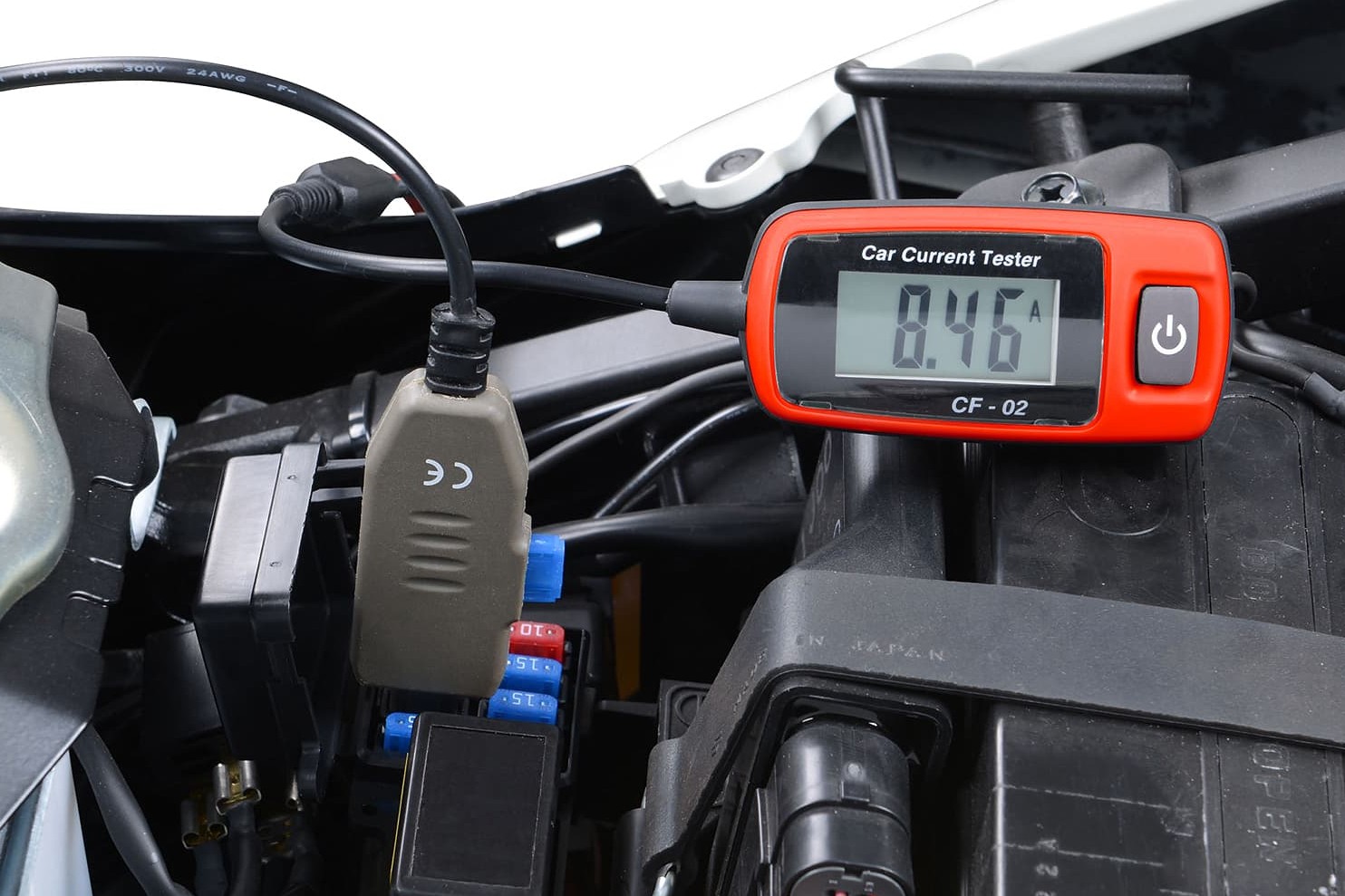
Circuit tester for detecting leakage currents
Testing instruments
Faults in two wheeler electrics normally arise due to trapped defective cables with damaged insulation or poor, and possibly also wet, plug-in connections. These lead every now and again to short-circuits or leakage currents. A leakage current (the "little brother" of the short-circuit) occurs if there is an unwanted connection somewhere in an electrical circuit due to moisture or corrosion, e.g. at an open contact such as the ignition switch (when switched off). Although very weak, it drains the battery over time when the vehicle is parked. This happens much faster with short-circuits. These are noticeable because the fuses pop out. The best way to pinpoint the cause of these kind of problems is to use a circuit tester. This detects and measures DC currents. Leakage currents in the electrical circuit can be detected with the adapters for mini and standard blade fuses when the ignition is switched off. All you have to do is pull one of the fuses out of the fuse box and plug it into the appropriate adapter. Then insert the adapter in the position from which you removed the fuse, switch on the device, and take a reading.
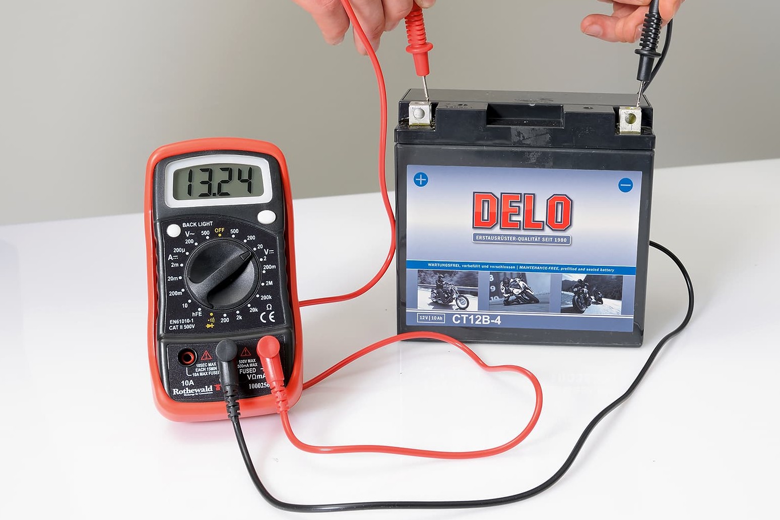
The multimeter, a versatile testing and measuring instrument
To find sources of faults and perform electrical checks on electrical components, a multimeter is useful for measuring the battery voltage, resistance of a cable or component, current flow and much more. You can obtain motorcycle-specific multimeters from Louis with instructions for use with application examples. This makes troubleshooting much easier.
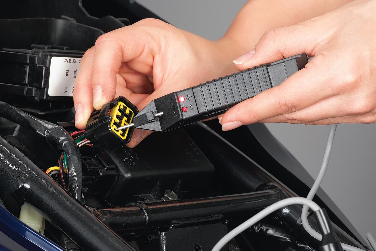
Faults in the wiring harness can be detected using the LED multifunction tester
If the aim is only to determine whether a component is receiving power or the supply line has been interrupted, a simple timing light is useful. It should be a part of every tool set. The cable of the LED multifunction tester is connected to the earth (e.g. a bare metal engine screw) or to a negative cable from the vehicle wiring harness (e.g. on the negative terminal of the battery) and the test probe is held at the positive input of the component being tested (e.g. the input cable of the ignition). If the lamp remains off, power is not being supplied to the component in question and the supply line must be checked for interruptions. If the lamp lights up, the power supply is ok and something may be wrong with the component internally.
Other malfunctions occur due to corroded cables for example, whose internal resistance is so high that they no longer conduct well and become hot. Older ignitions and switches frequently do not conduct the current sufficiently which leads to failures. If the alternator, or only its cable connection, is defective, this can cripple the power supply to the battery. Defective voltage regulators can cause overcharging of the battery. Worn carbon brushes can cripple a starter motor. For more information, see Testing the electrics and electronics in our DIY tips.
The Louis Technical Centre
If you have a technical question about your motorbike, please contact our Technical Centre, where they have endless experience, reference books and contacts.
Please note!
These tips for DIY mechanics contain general recommendations that may not apply to all vehicles or all individual components. As local conditions may vary considerably, we are unable to guarantee the correctness of information in these tips for DIY mechanics.
Thank you for your understanding.


