Connecting LED turn signals on your motorcycle
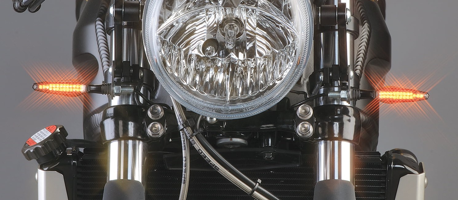
LED technology opens up a whole new world of vehicle design opportunities. Turn signals are an excellent example, and the good news is that retrofitting LED turn signals is a piece of cake for DIY mechanics.
Note: The videos are in German.
- Perfect for the motorcycle: Light Emitting Diodes
- Buying turn signals
- Technical requirements
- Flasher relay or resistors?
- Installing LED turn signals – now let's get started
- 01 – Remove cockpit fairing
- 02 – Mount covers are a ready-made solution
- 03 – Adapter cables leave the wiring harness intact
- 04 – Take off tail fairing and remove turn signals
- 05 – Fit the new mini turn signals and mount covers
- 06 – Installing resistors
- 07 – When you buy resistors from Louis
- 08 – Resistors fitted underneath the seat
Important: You do need a basic knowledge of vehicle electrics to do this job yourself. If you don't feel confident, or if your motorbike has complicated electronics, you should definitely leave it to a specialist motorcycle workshop. If your motorcycle is still under warranty, you should first check with your authorised dealer about whether conversion would affect it.
Perfect for the motorcycle: Light Emitting Diodes
Modern LED (Light Emitting Diode) technology has opened up a whole new world of possibilities in turn signal design. Low power consumption takes a load off the electrical system, small-diameter cables reduce cost and save weight, the powerful light output allows tiny dimensions and imaginative designs, and long LED life saves you the bother of frequent replacement. Especially on a motorbike, small housings are a great bonus – a traditional "bulb" turn signal looks like a soup bowl compared to today's, street-legal LED mini turn signals.
So it's no wonder that many bikers decide to switch to stylish LED turn signals when an original turn signal needs to be changed and the dealer's price for the OEM spare part comes as quite a shock – if they haven't already made the switch, that is.
In principle any bike with a 12 V DC electrical system can be fitted with LED turn signals.
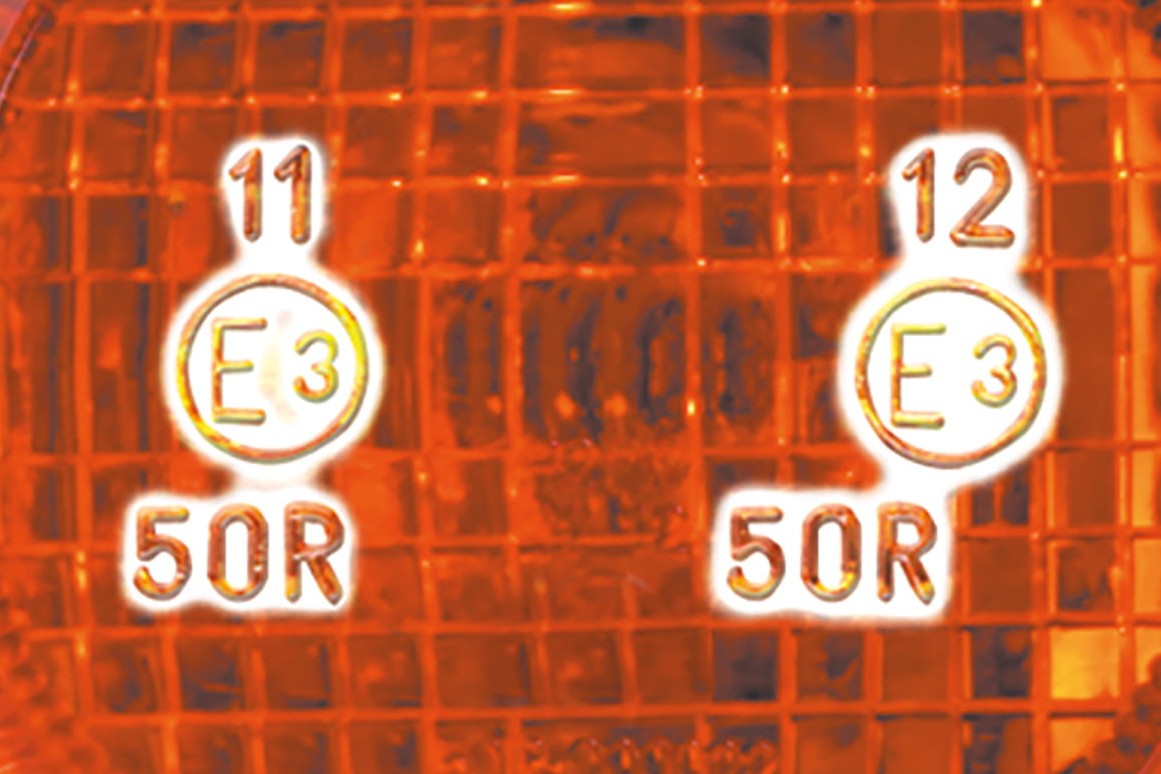
Important: Only use turn signals with an "E" mark
Buying turn signals
When you buy yourself new turn signals, always check that the lenses carry an "E" mark indicating that they are type-approved. All turn signals in the Louis range have a valid "E" mark. Approved "front" turn signals bear the code 1, 1a, 1b or 11, and approved "rear" turn signals bear the code 2, 2a, 2b or 12. Many turn signals in the Louis range are approved for both front and rear, so have two codes. Bar-end turn signals with an "E" mark are only approved for the front of your motorbike, and you must have rear turn signals in addition. If you have a choice of turn signals with stalks of different lengths, please bear the following in mind: under EU rules, front turn signals must be at least 240 mm apart, rear turn signals at least 180 mm.
Technical requirements
LEDs have a substantially lower wattage (power consumption) than conventional incandescent bulbs. If one turn signal bulb blows, the other turn signal on your motorbike flashes much too fast – something which you will no doubt have experienced (By law, turn signals must flash at a rate of not less than 60, and not more than 120 flashes per minute). This is because the flasher has lost half of the "load" which keeps it at the right tempo. The effect is exaggerated if, for example, you replace two 21 watt stock turn signals (one per side) with two LED turn signals, each rated at 1.5 watts. Now the load on the original flasher is only 3 watts (2 x 1.5) instead of 42 watts (2 x 21). Generally speaking, this won't work.
There are two ways to solve the problem: You either install a special load-independent LED flasher relay, or you "fool" the original flasher into thinking the LEDs have the correct wattage by installing electrical resistors.
Flasher relay or resistors?
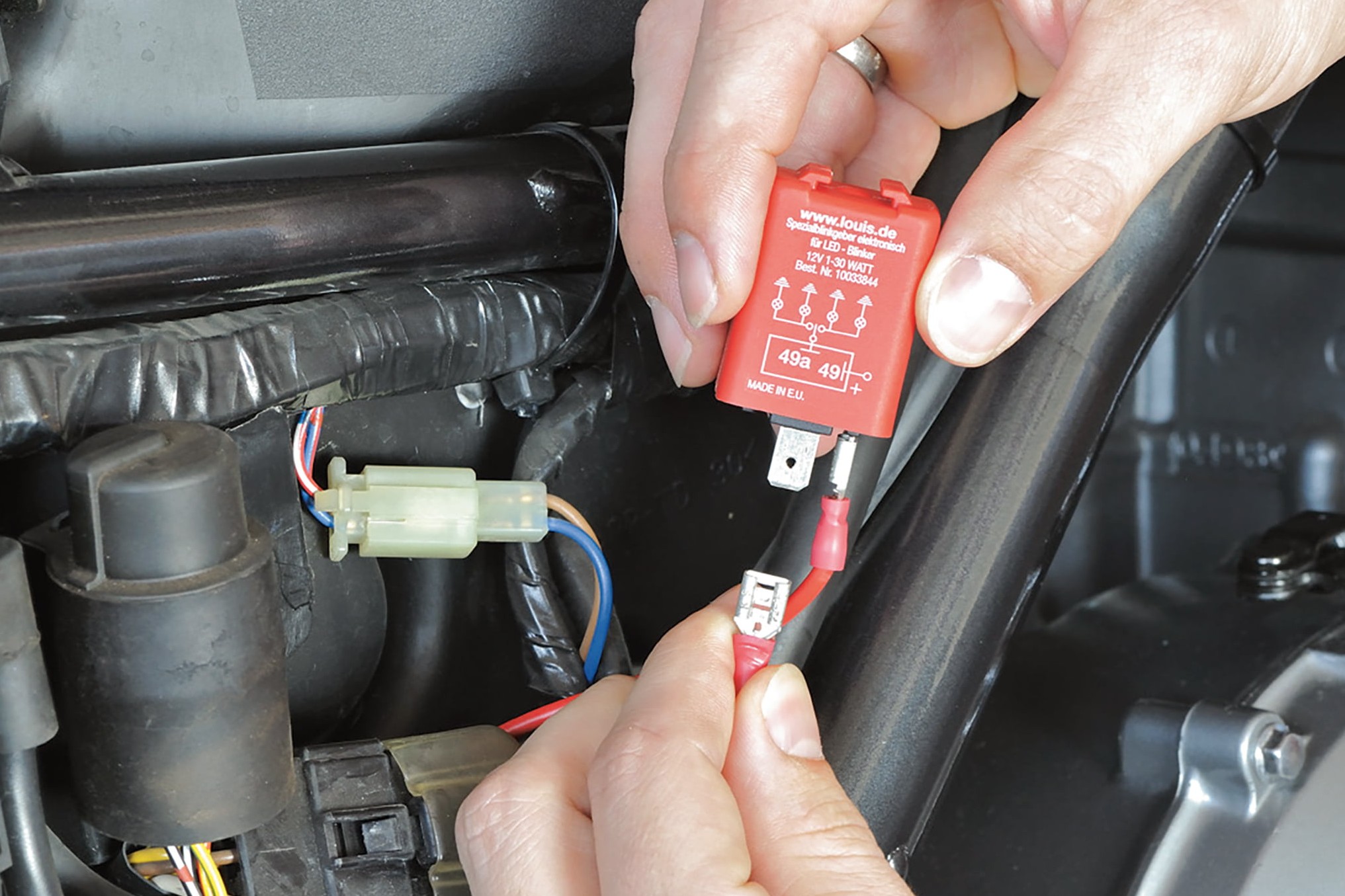
Vital for the relay: correct polarity
Replacing the relay is the simpler option, but is only possible under the following conditions:
- The motorcycle cockpit must have two separate indicator lights for the left/right turn signals, not a single combined light
- The motorcycle must not be fitted with a turn signal beeper or hazard warning flasher
- The original relay must not be integrated in a combined unit (you can recognise a combined unit by its three outgoing cables)
You can use our inexpensive Universal Relay for LED turn signals if your motorbike meets all three of the above requirements. The slightly more expensive Kellermann Universal Turn Signal Relay is compatible with most hazard warning flashers, turn signal beepers and only a single indicator light (items 1 and 2 above).
If your motorbike does not comply with items 2 and 3, we can offer you a manufacturer-specific plug and play relay, which fits the original connector or port. Unfortunately, we are not able to specify the relay you require for a specific motorcycle model. Please go to www.louis.eu and enter "LED flasher relay" to see what relays are available, and compare these with your original relay. For Suzuki models, for example, we can also offer you the combined relay unit with 7 contacts.
Relay
You must ensure that the polarity of the relay is correct – incorrect connection will immediately damage the relay electronics and void any manufacturer's warranty. Even if the arrangement of connections is the same as on the original relay, the polarity may still be different. Always check the polarity with an LED test light first (to do so, follow the flasher installation instructions).
If the plug-in connectors do not fit, it is relatively easy to make adapter cables to save you having to cut off the original connector on the wiring harness.
Many modern motorcycles are not fitted with flasher relays at all. Instead, they are integrated in the central electronic unit. In this case, you have no choice but to use resistors.
Resistors
If you are not able to operate your new LED turn signals via the aforementioned relays, you would have to use resistors to regulate the flashing frequency (in which case, you need to retain the original relay). Almost all the turn signals in our range will function with the original flasher relay in combination with the 6.8 ohm resistor.
Important: If you are changing the relay, you can skip the step described below for installing the resistors.
Installing LED turn signals – now let's get started
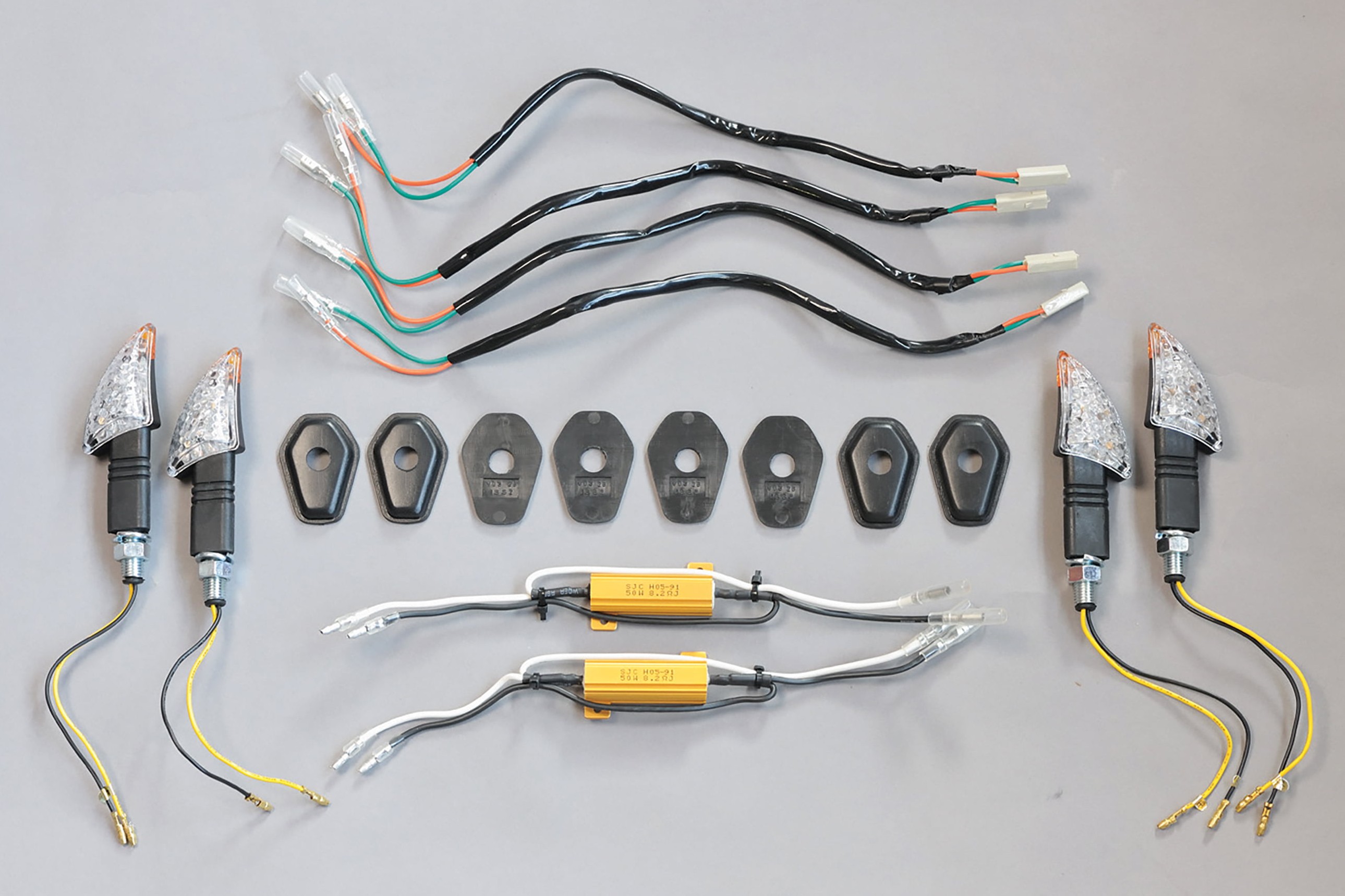
For our example, we need: 4 LED turn signals, 2 resistors, 4 adapter cables, 4 mount covers
We will now show you how to install LED turn signals with resistors on a Kawasaki Z750. The LED turn signals we are using are curved, which is why there is one model for front left and rear right and another for front right and rear left.
Unfortunately, when you remove your original turn signals, you're left with unsightly holes almost big enough to throw the new mini turn signals through. This is where turn signal mount covers come in handy. These covers are not specifically designed for the Z750 but they are easy to adapt. If you cannot find anything suitable for your motorbike, you can make your own covers out of aluminium, plastic or sheet metal.
In our example, we can use prefabricated adapter cables, which are available from the Louis range for many different motorbike models. They make it far easier to connect the new turn signals because they can be fitted directly to the compact connectors on the wiring harness. Likewise, the other connectors will fit the resistors and turn signals without any modification. If you are not able to use adapter cables, please refer to the instructions in Step 4.
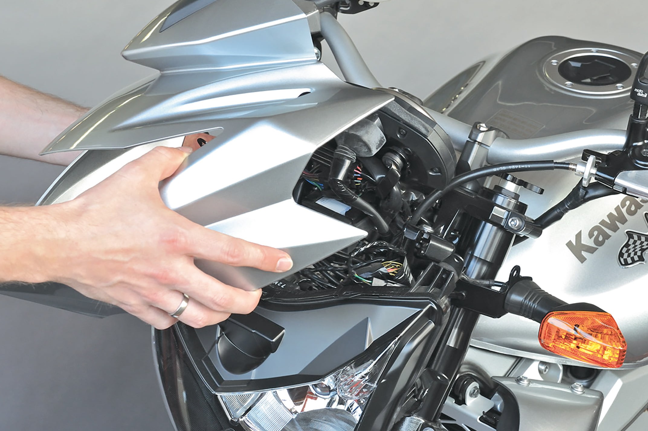
Step 1: Remove cockpit fairing
01 – Remove cockpit fairing
- As with all work on the bike's electrical system, the negative cable must first be disconnected from the battery to avoid a short-circuit.
- To replace the front turn signals, take off the front fairing and set it down in a safe place (on a cloth or blanket).
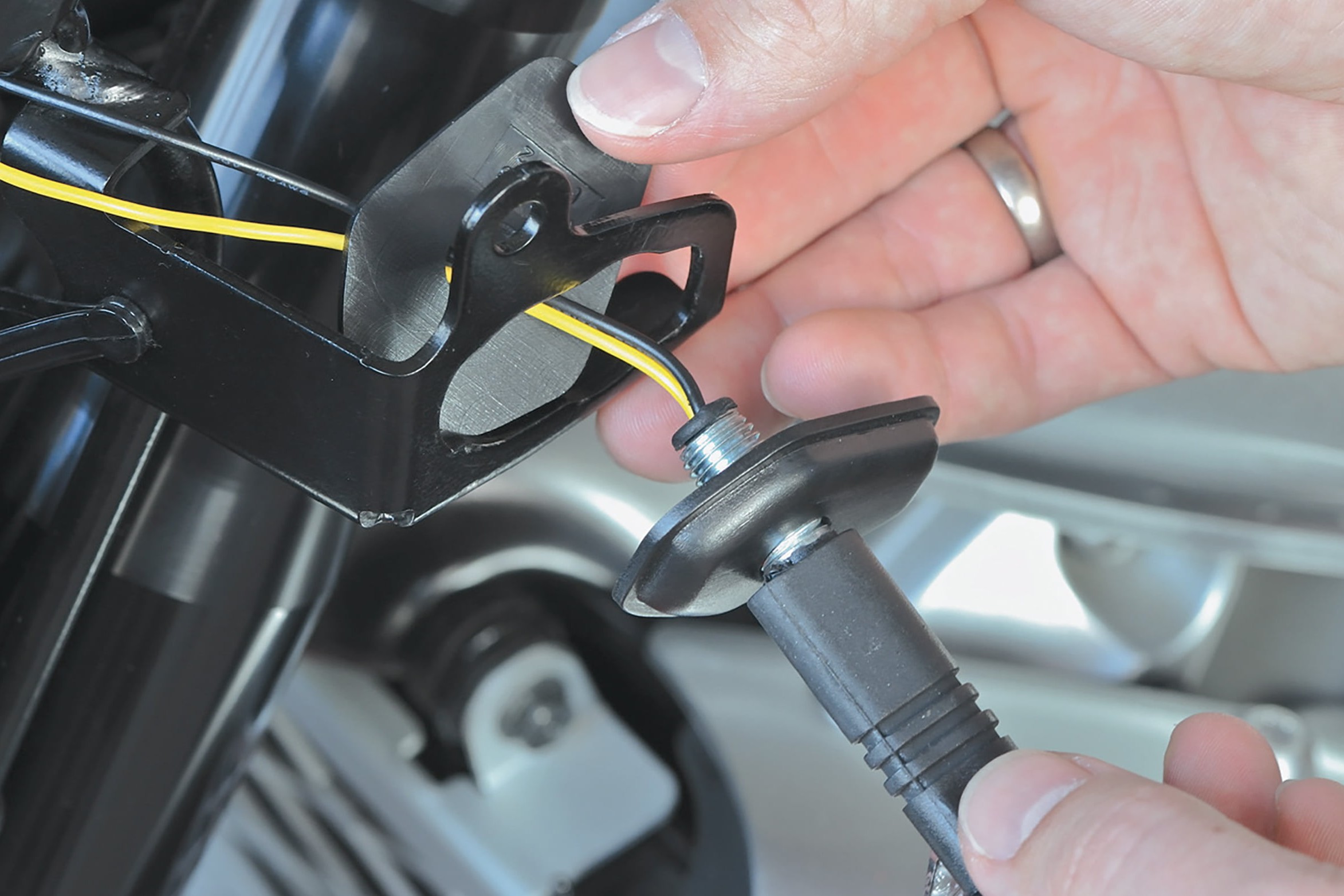
Step 2: Mount covers are a ready-made solution
02 – Mount covers are a ready-made solution
Now you can remove the original turn signals and screw on the new ones including the mount covers. When tightening them, remember they are not truck wheel bolts, so don't use too much elbow grease
Incidentally, mini turn signals often have a fine thread M10 x 1.25 (standard nuts are M10 x 1.5). So if you lose a nut underneath the workbench, please order a replacement.
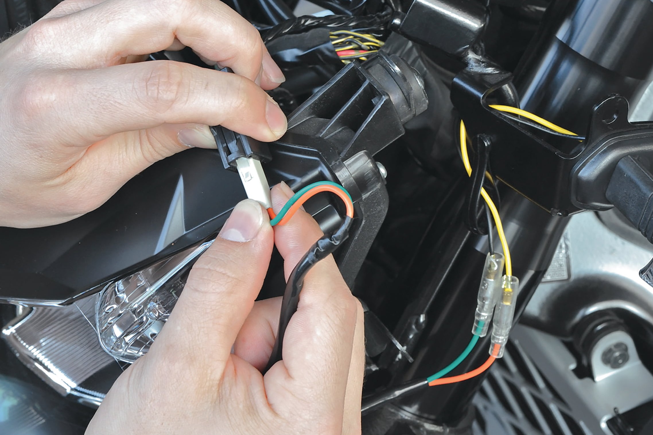
Step 3, Fig. 1: Adapter cables leave the wiring harness intact
03 – Adapter cables leave the wiring harness intact
Next, connect up adapter and turn signal cables. LED turn signals will only work if the polarity is correct. As the motorcycle manufacturers do not use standardised cable colours, a circuit diagram, if available, is useful for localising the positive and negative cables.
Proceed in the same way for the other side, and then you can put the fairing back on. The cross-head screws all engage in plastic threads, so take care when tightening them.
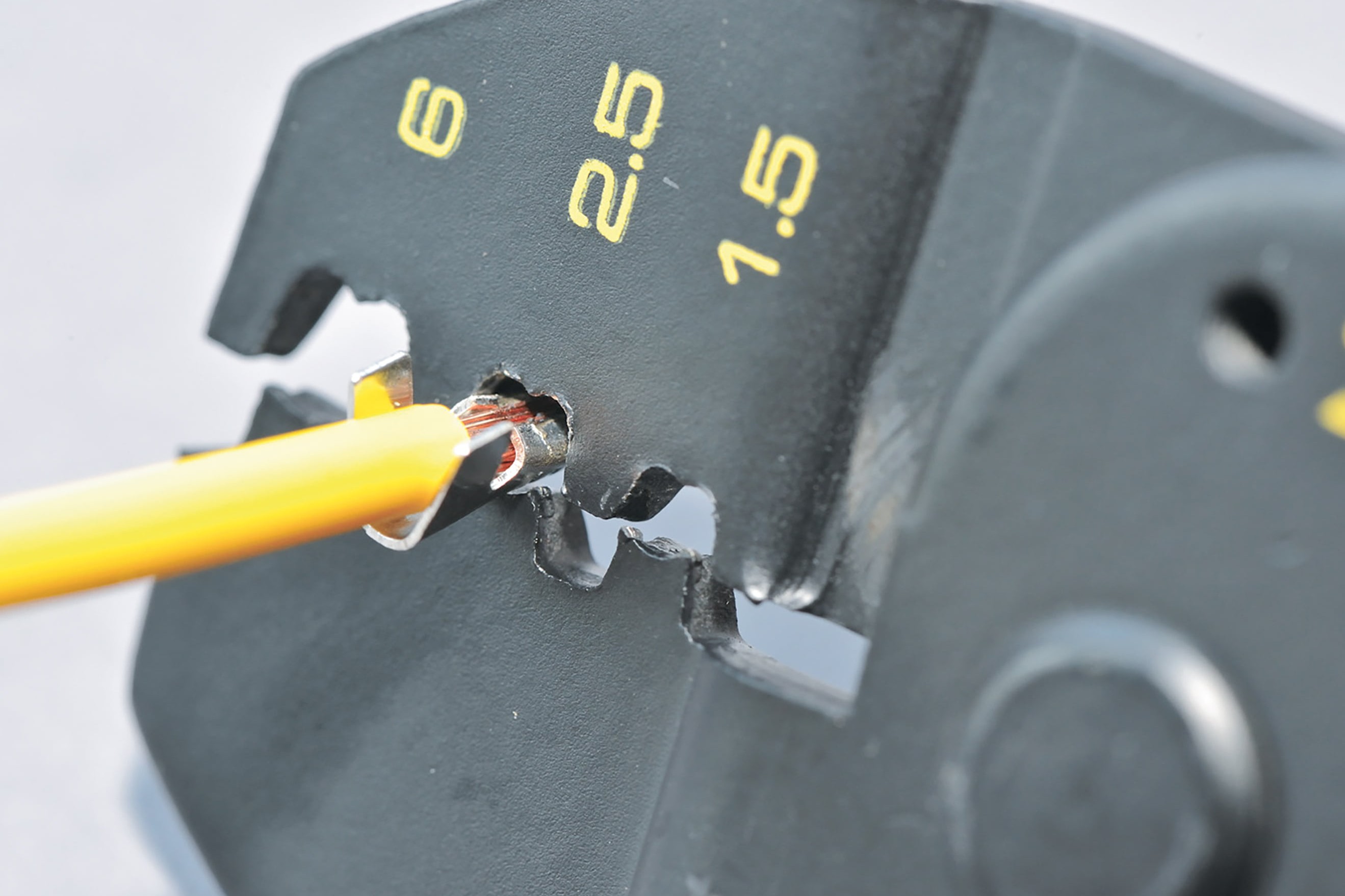
Step 3, Fig. 2: Multifunctional crimping tool for Japanese connectors, without coloured markings
Important: If you cannot use adapter cables, it is important to make a safe, permanent cable connection. One option is to solder the cables and then to insulate them with heat shrink tubing; another is to use crimp-type cable terminals. For this, Japanese connectors should be used, for which you will need a special crimping tool. Both of these are also available together in our professional set. There is also a crimping tool that is suitable only for insulated cable terminals, but NOT for Japanese connectors. You can recognise it by a red, blue and yellow dot on the tip of the tool. You can find out more about connecting cables in our DIY tips Cable Connections.
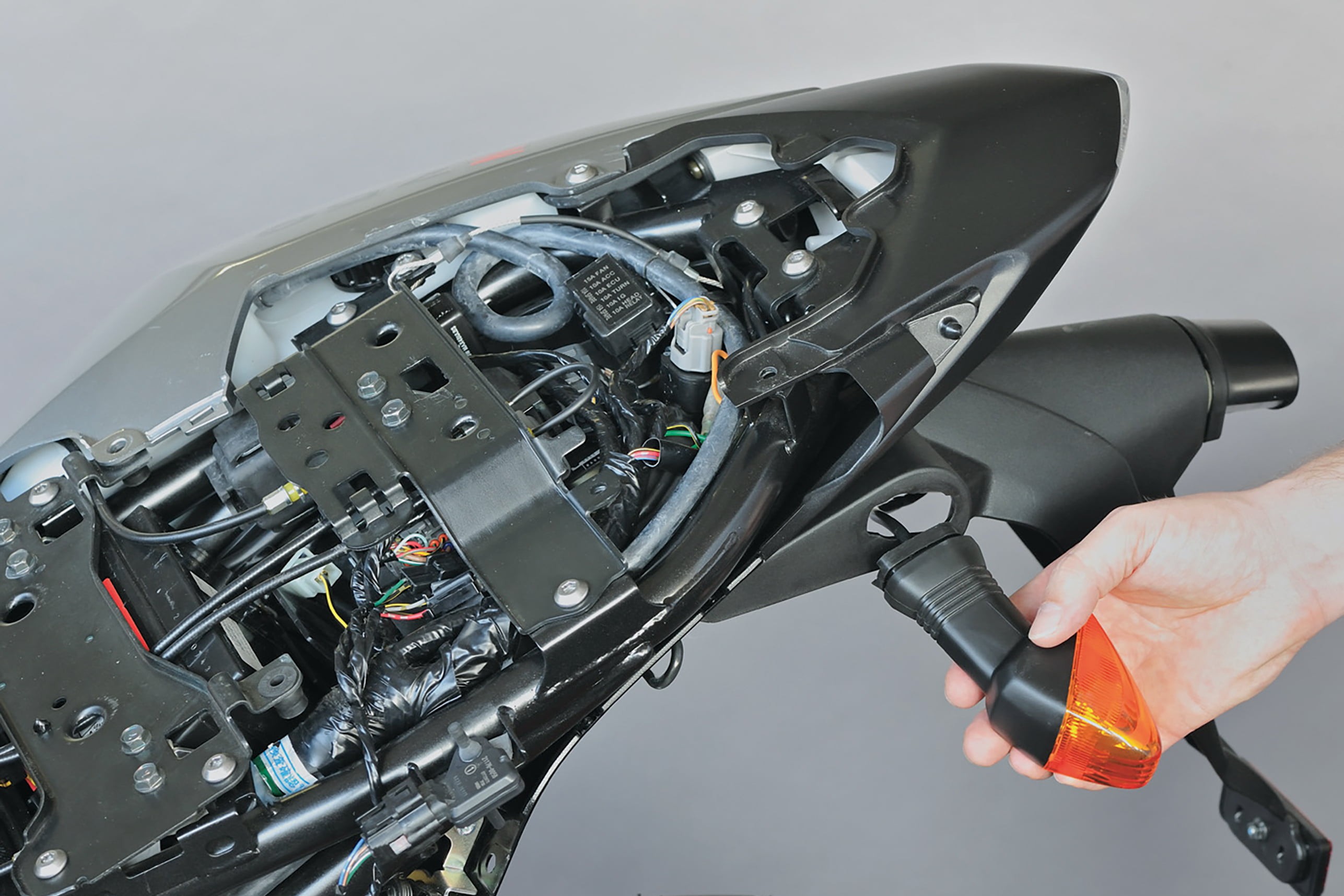
Step 4: Take off tail fairing and remove turn signals
04 – Take off tail fairing and remove turn signals
To fit the rear turn signals and resistors, take off the seat and unscrew the tail fairing. Once again, carefully set down this expensive and delicate piece of plastic.
05 – Fit the new mini turn signals and mount covers
In the same was as for the front turn signals, now remove the rear turn signals and fit the new mini turn signals and mount covers. Route the cables in their original positions.
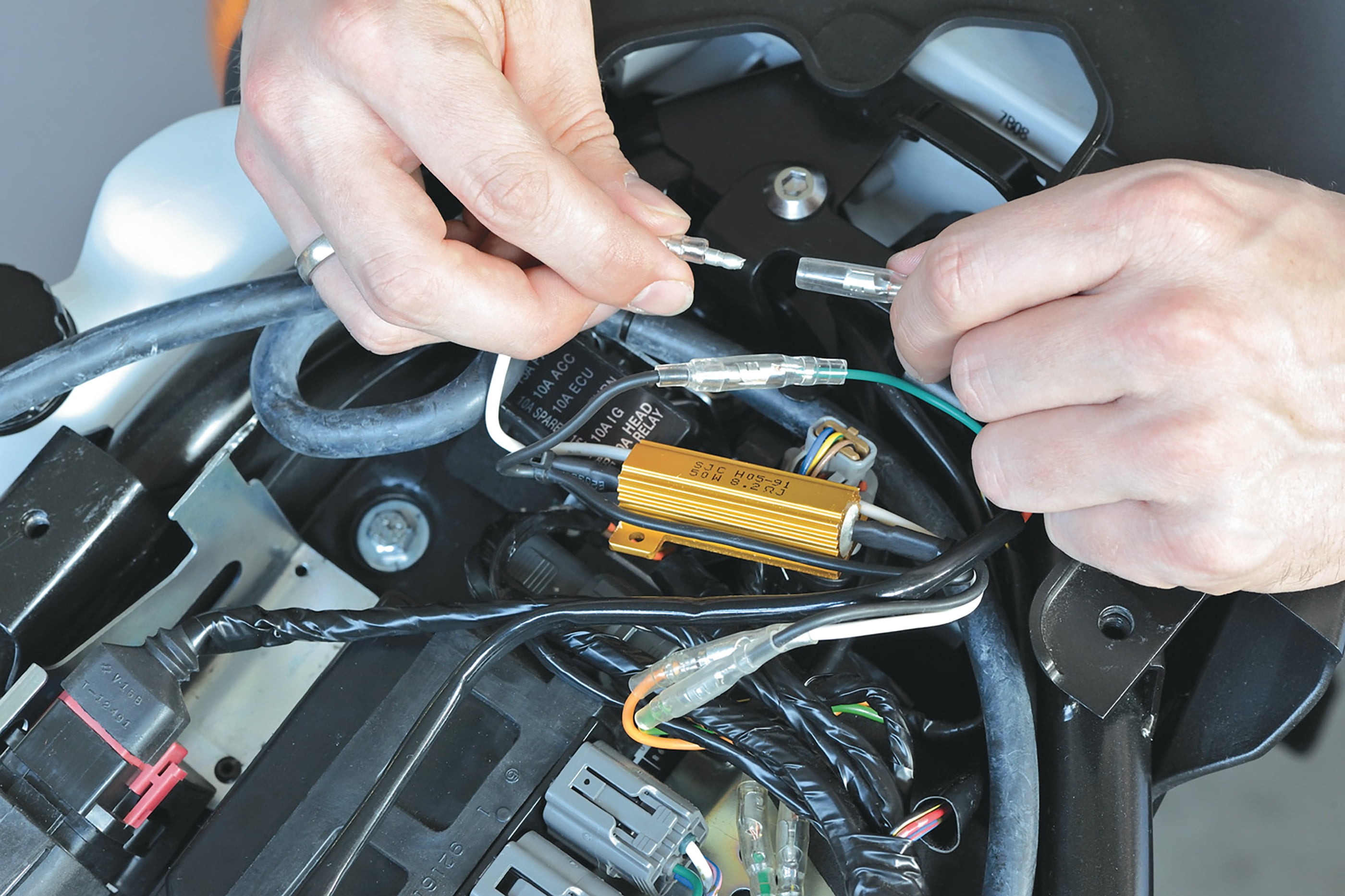
Step 6, Fig. 1: Resistor connection at the rear
06 – Installing resistors
Now the resistors need to be installed on the rear turn signals. Do NOT connect them in series. They must be connected in parallel to give the correct flashing frequency. If you buy resistors from Louis, they come prewired in parallel (see the picture below).
The resistors have no polarity, so it doesn't matter which way round you fit them. The cable terminals provided with the Louis resistors make for easy installation.
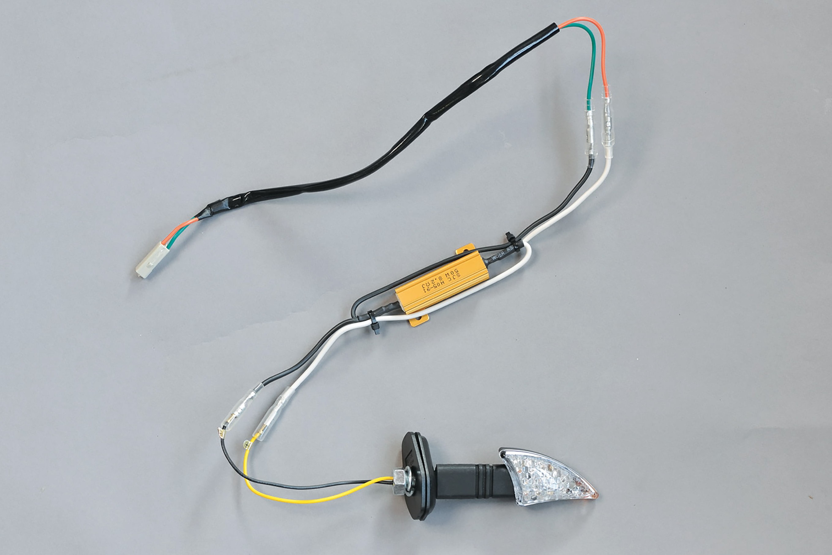
Step 6, Fig. 2: Correct wiring at a glance: turn signal, resistor, adapter cable
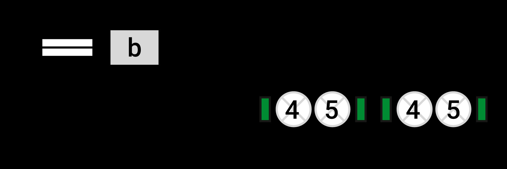
Step 7: When you buy resistors from Louis, they are already pre-wired in parallel
07 – When you buy resistors from Louis
1 = R
| a = Fuse b = Flasher relay c = Turn signal switch d = Turn signal (bulb) e = Resistor f = Earth lead g = Power source/battery |
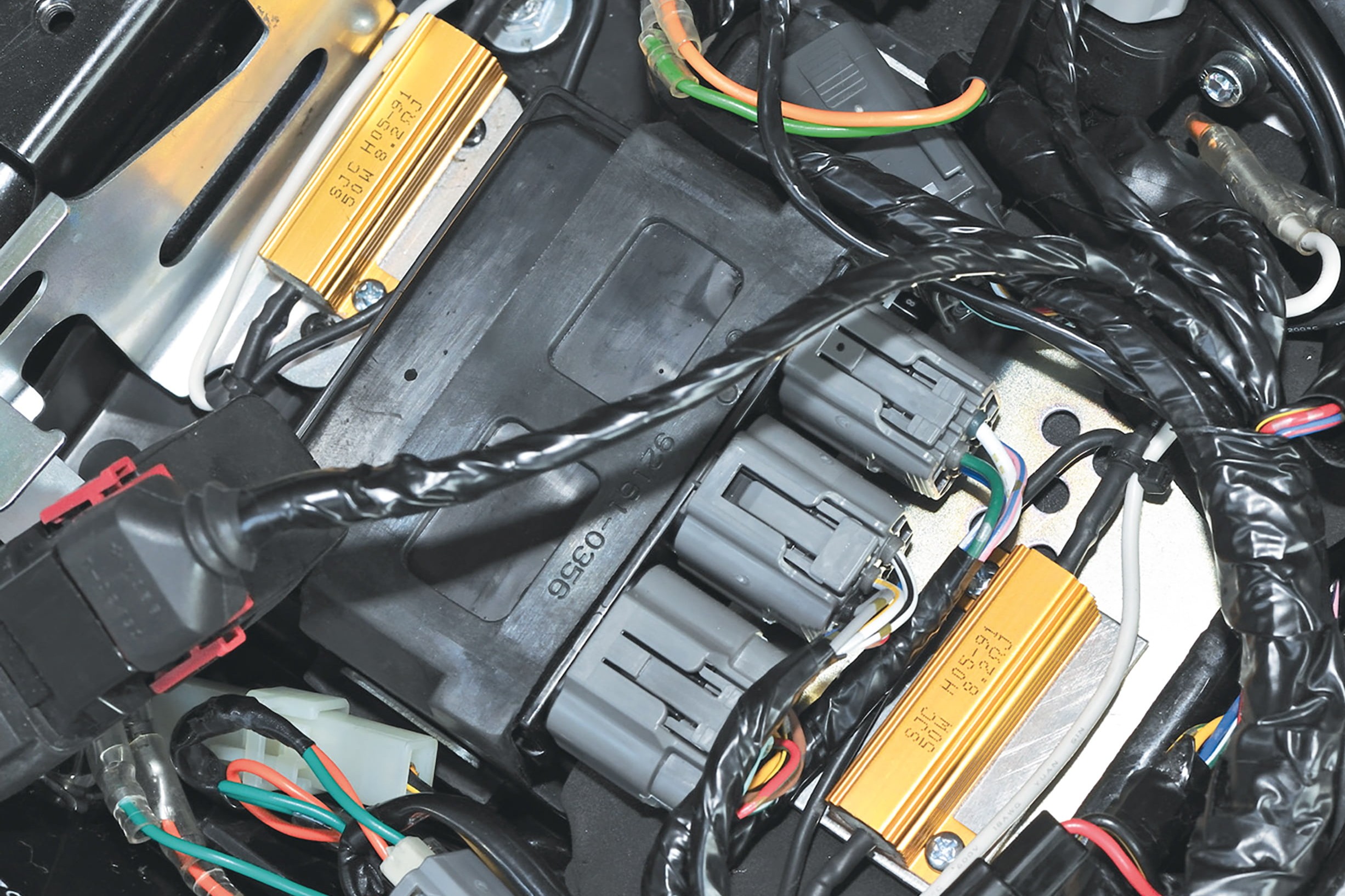
Step 8, Fig. 1: Resistors fitted underneath the seat
08 – Resistors fitted underneath the seat
The resistors can reach temperatures above 100° C when in operation (prolonged use of turn signals, or hazard warning flasher if you break down), so they need plenty of air to keep them cool. They should not be completely enclosed or mounted in direct contact with a plastic surface. So it's a good idea to make a small mounting plate out of sheet aluminium and place that in the bike.
The Z750 has a metal plate on the right, next to the control unit, which is an ideal place to install it. This is where we fitted the resistor for the right turn-signal circuit using 3 mm nuts and bolts. We fitted the resistor for the left turn-signal circuit on the left side next to the control unit. However, the resistor cannot be screwed directly to the visible metal plate on this side, as there is another control unit underneath the plate, which could get damaged. So we screwed the resistor to a metal plate and then inserted the whole thing under the black box.
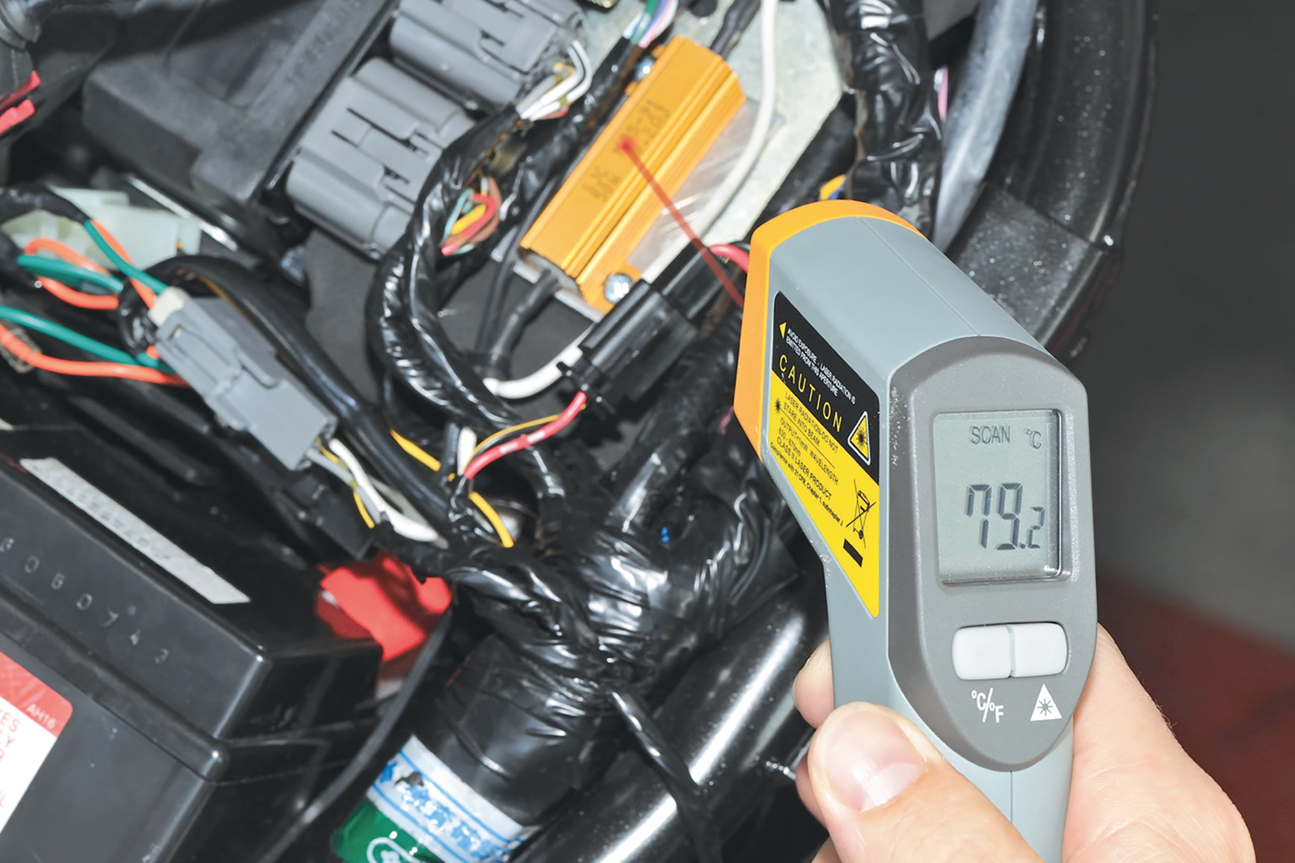
Step 8, Fig. 2: Infrared thermometer reads 79°C after only a few minutes
Once you have wired and connected the resistors (don't forget the battery earth cable), it's time for a test. We monitored the temperature of the resistors with an infrared thermometer. They heat up to almost 80°C in just a few minutes.
So you should never use double-sided adhesive tape, for example, for securing the resistors in your fairing. It will not be strong enough, and may end up causing damage! Once everything is working correctly, you can refit the tail skirt. The conversion is now complete!
The Louis Technical Centre
If you have a technical question about your motorbike, please contact our Technical Centre, where they have endless experience, reference books and contacts.
Please note!
These tips for DIY mechanics contain general recommendations that may not apply to all vehicles or all individual components. As local conditions may vary considerably, we are unable to guarantee the correctness of information in these tips for DIY mechanics.
Thank you for your understanding.


